Climbing Cams
Skills Involved

Project Management
Setting design requirements based on use cases, managing budget, sourcing materials and tooling

Mechanical Design
DFM, CAD work in Fusion 360, motion analysis, muli-part assemblies, free body diagrams, load calculation, stress calculations

Manufacturing
Waterjet construction, manual machining, brazing, wire rope work, spring fabrication, 3D printing
What are Cams, and why Build them?
What are Cams?
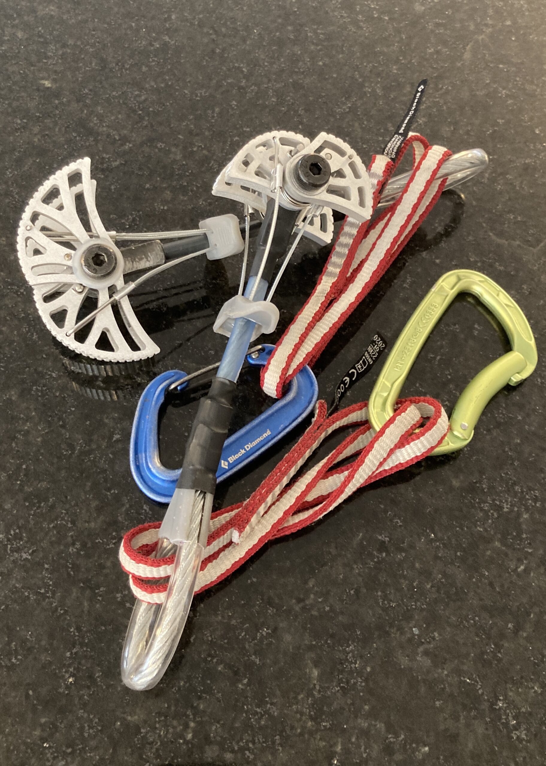
Cams, or camming devices, are a type of rock climbing equipment used to catch a climber if they fall. They consist of a number of cam lobes that expand under load when inside cracks in the rock wall.
Why Build Them?
Having to reverse engineer and redesign cams to meet my manufacturing and material constraints gave me a much better understanding of the loads and stresses within the device. It made me consider material properties and how the availability of components can be a major constraint on a design. Especially while managing costs.
How to build a Camming device
Set Requirements and Constraints
Camming devices (cams) are complex mechanical assemblies that must be easy to use while meeting the high load requirements needed to catch a climber’s fall. Commercial cams have evolved over the years and use high-performance materials and manufacturing to create a product that can perform as intended.
Requirements
- Strength – Based on low end of commercial cams and estimations of user generated loads
- Can support 8kn load applied in line with the stem
- Usability – Based on experience with existing cams
- Must be able to deploy with one hand
- Camming range of ~ 1″
- Must have enough spring force to hold itself in to place when deployed
Constraints
- Cost – Commercial cams run between $90 – $200 each
- Under $150
- Manufacturability
- Must be able to manufacture and assemble in a student run shop space
(Source: BigWalls.net)
Cam Geometry
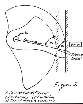
Cams must be able to catch a fall across a range of deployment positions. As such the contact angle at the cam lobes must be constant throughout its range of motion. The curve of a logarithmic spiral has this property. Various companies have found between 14-15° as the optimal contact angle.
Load Calculations
To hold an 8kn load, each lobe must provide 2kn in the vertical direction. Most of the force generated at the lobe-rock interface is in the horizontal direction due to the 14.5° angle. This creates friction that keeps the lobes from slipping while the small vertical component arrests the fall. As a result, each lobe sees almost 8kN of force.
Calculation and FEA Validation
Based on the loads, tension, shear and bending stresses were calculated. Once a design was finalized, an FEA analysis was used to validate these calculations. From the calculation, the shaft had a required diameter of 3/8″, resulting in a safety factor of 1.2. The FEA found a safety factor of 1.
Sourcing Components
With the design completed, components were sourced from a mix of online retailers and local sources.
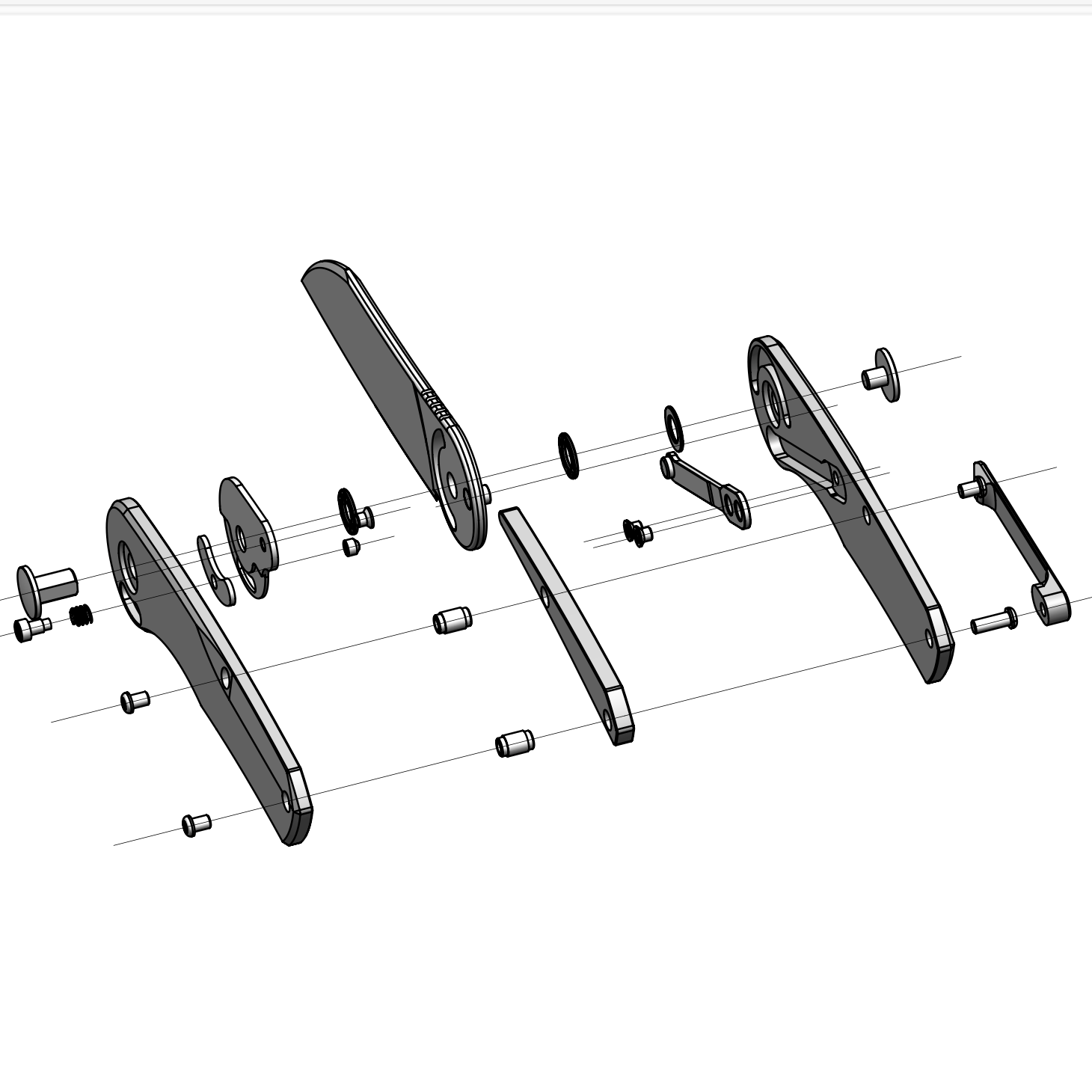
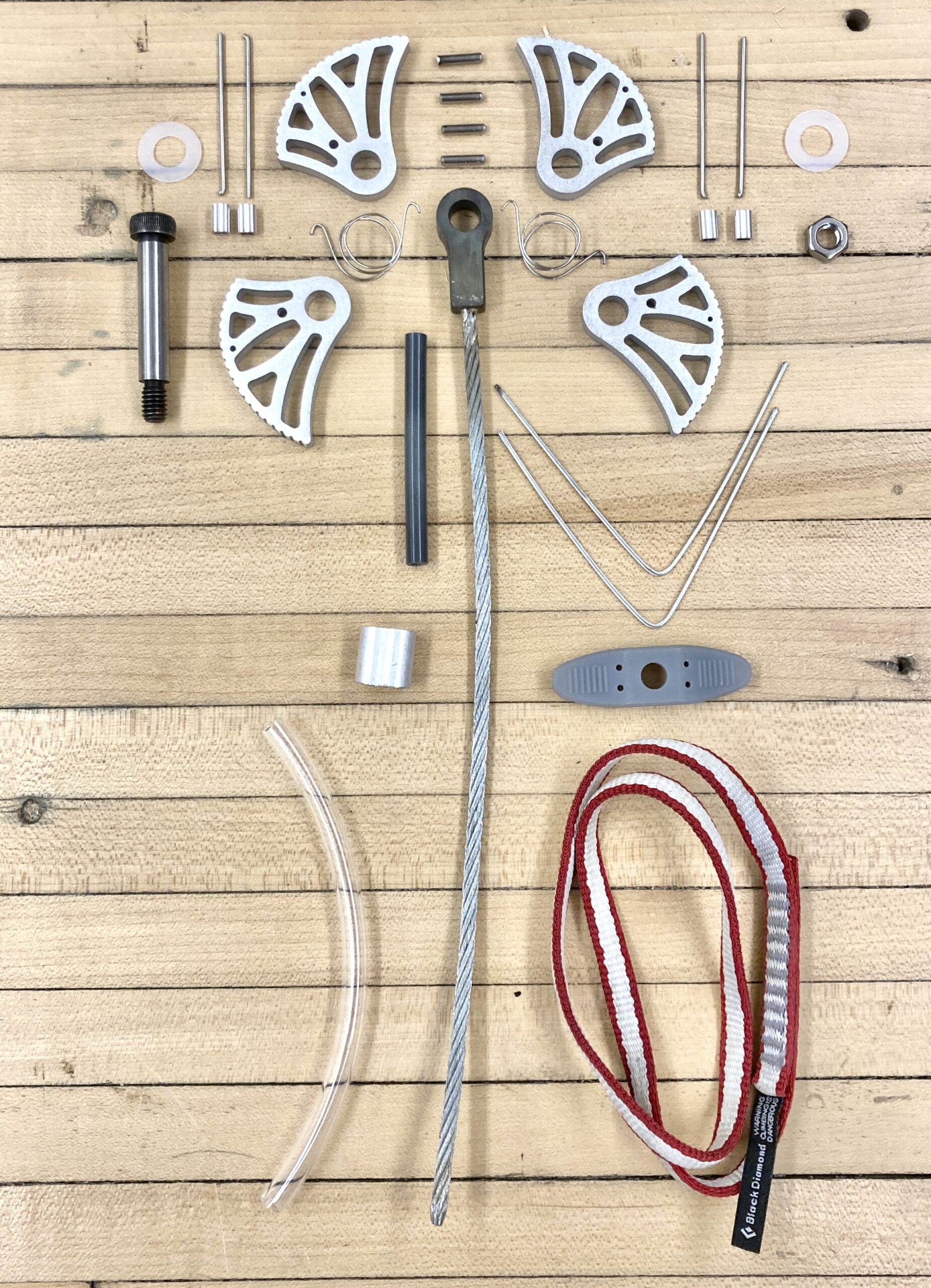
Fabrication
The cams are comprised of 31 pieces all requiring different manufacturing methods. Waterjet cutting, manual machining, brazing, wire rope work and 3D printing were all used to create the final product.
Waterjet cutting and manual machining
The lobes and eye were able to be waterjet cut out of 1/4″ aluminum for the lobes and 3/8″ steel for the eye. The circular features were then drilled and reamed to size.
Brazing
To transfer load from the falling climber to the rock, a wire rope with a steel eye carries load to the lobes that engage with the rock. The steel eye is brazed to the wire rope with silver solder. This joint was the most challenging part of the fabrication process. Over multiple attempts, temperature, surface finish, oxidation prevention and tolerances were perfected to achieve a proper connection.
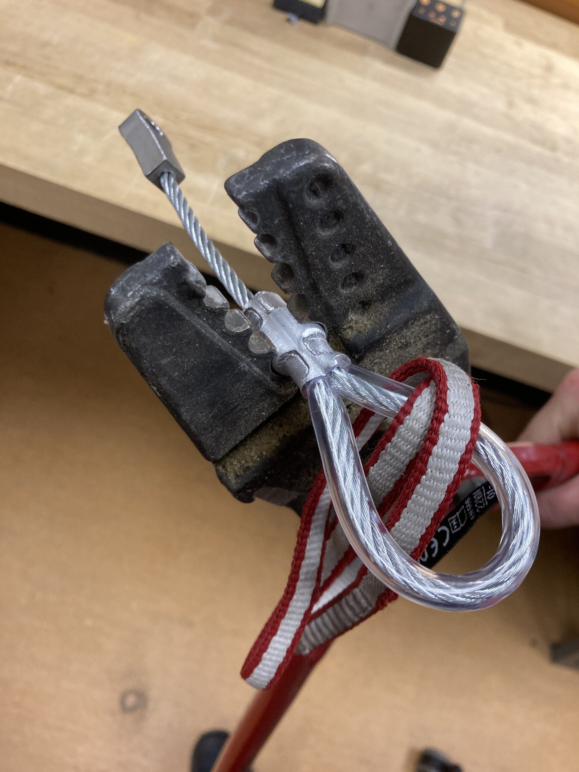
Swaging
To provide a point for a climber to attach to the cam, the wire rope is bent into a loop. A large crimp, called a swage is used to close this loop without losing strength in the wire rope.
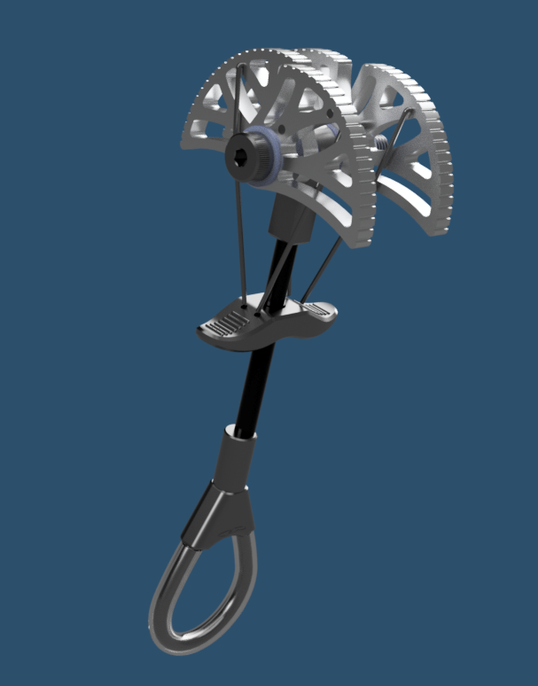
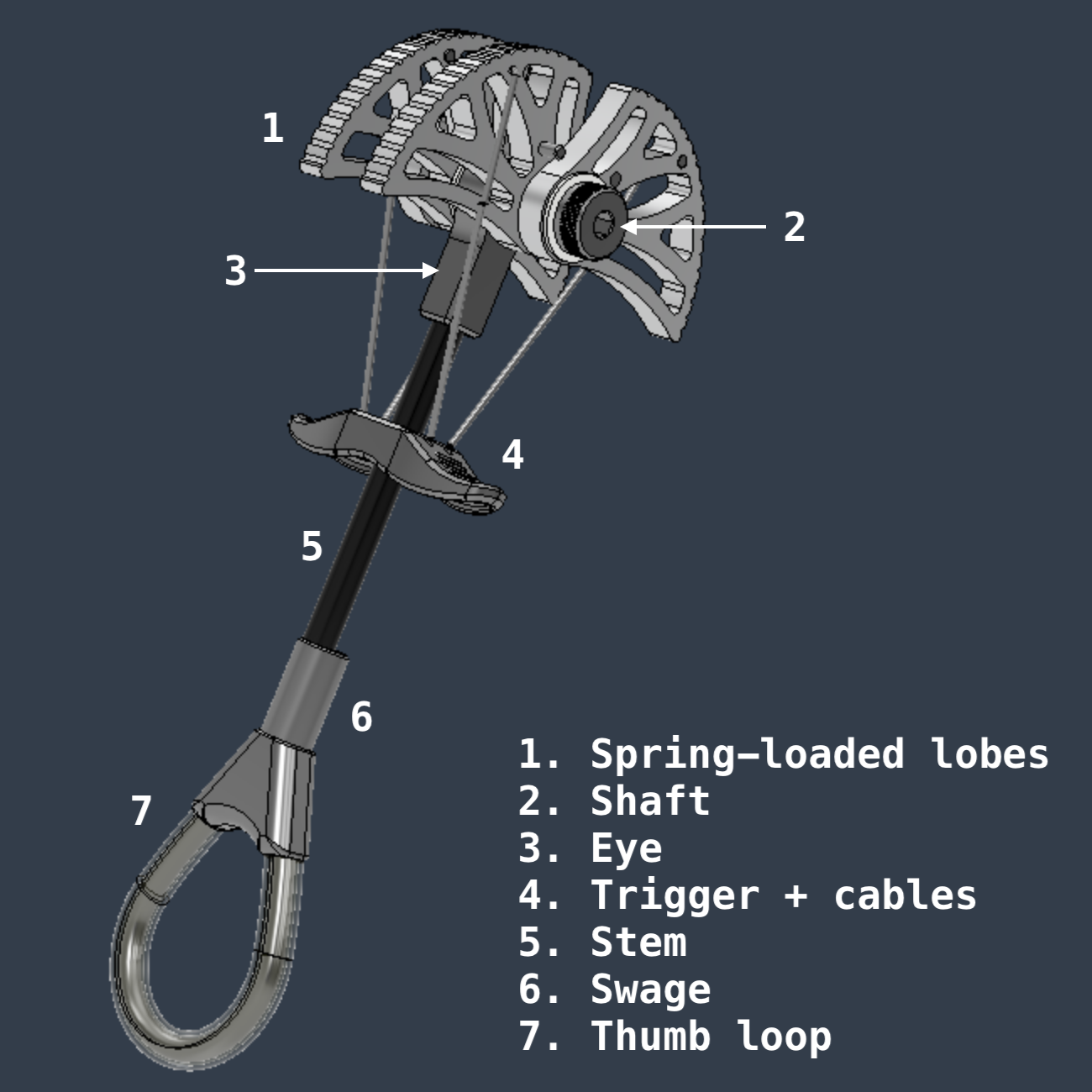
Making it usable
Supporting the load from a falling climber is only half of a cam’s function. It must also be easy to use and set up while climbing. For this, a whole host of other parts are required.
- Custom fabricated coil springs must be manufactured to hold the lobes in place
- A trigger is 3D printed and wires are connected to actuate the lobes
- A sheath adds rigidity to the stem
- PCV tubing is added to the thumb loop for comfort and to prevent abrasion
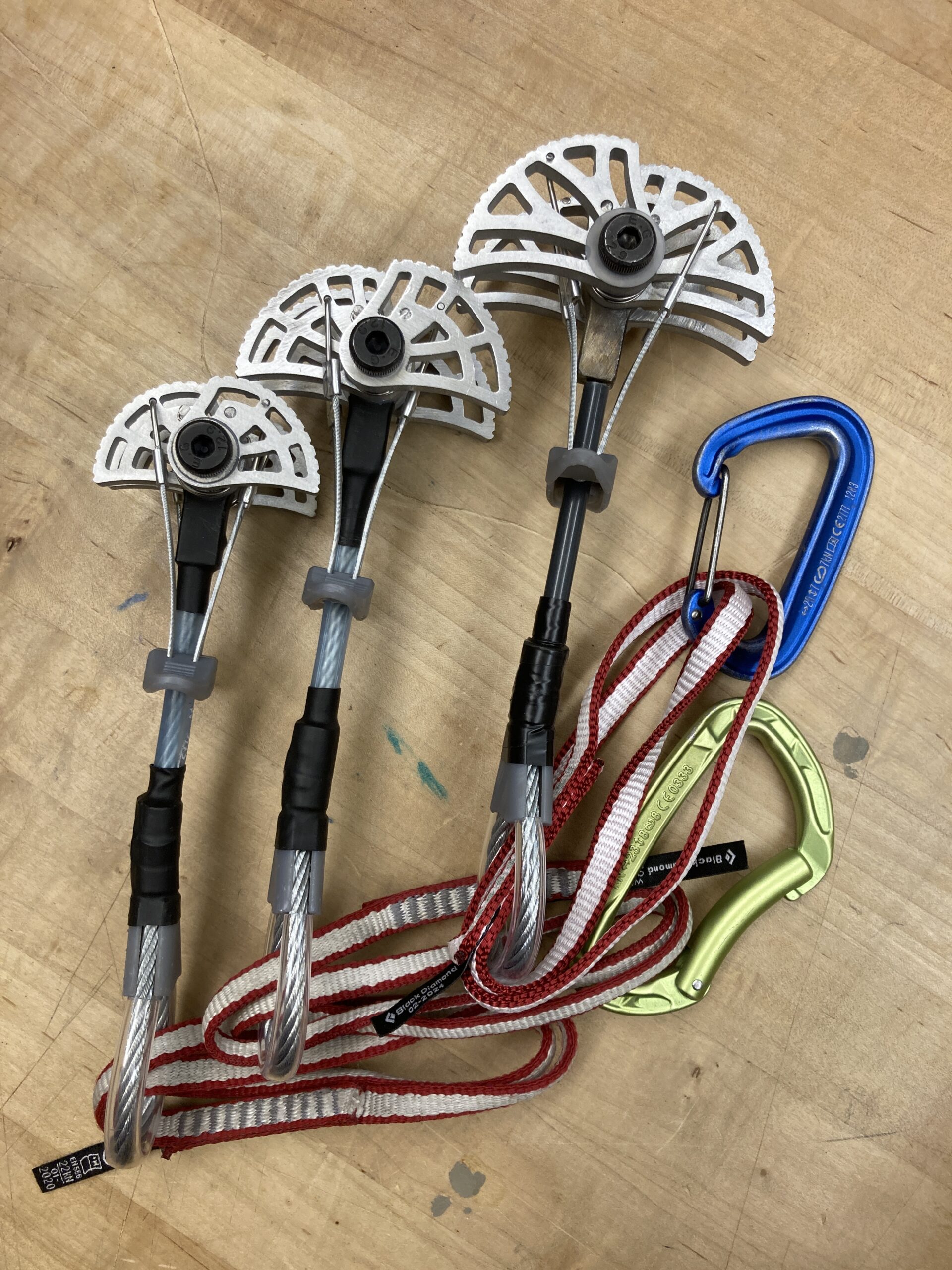
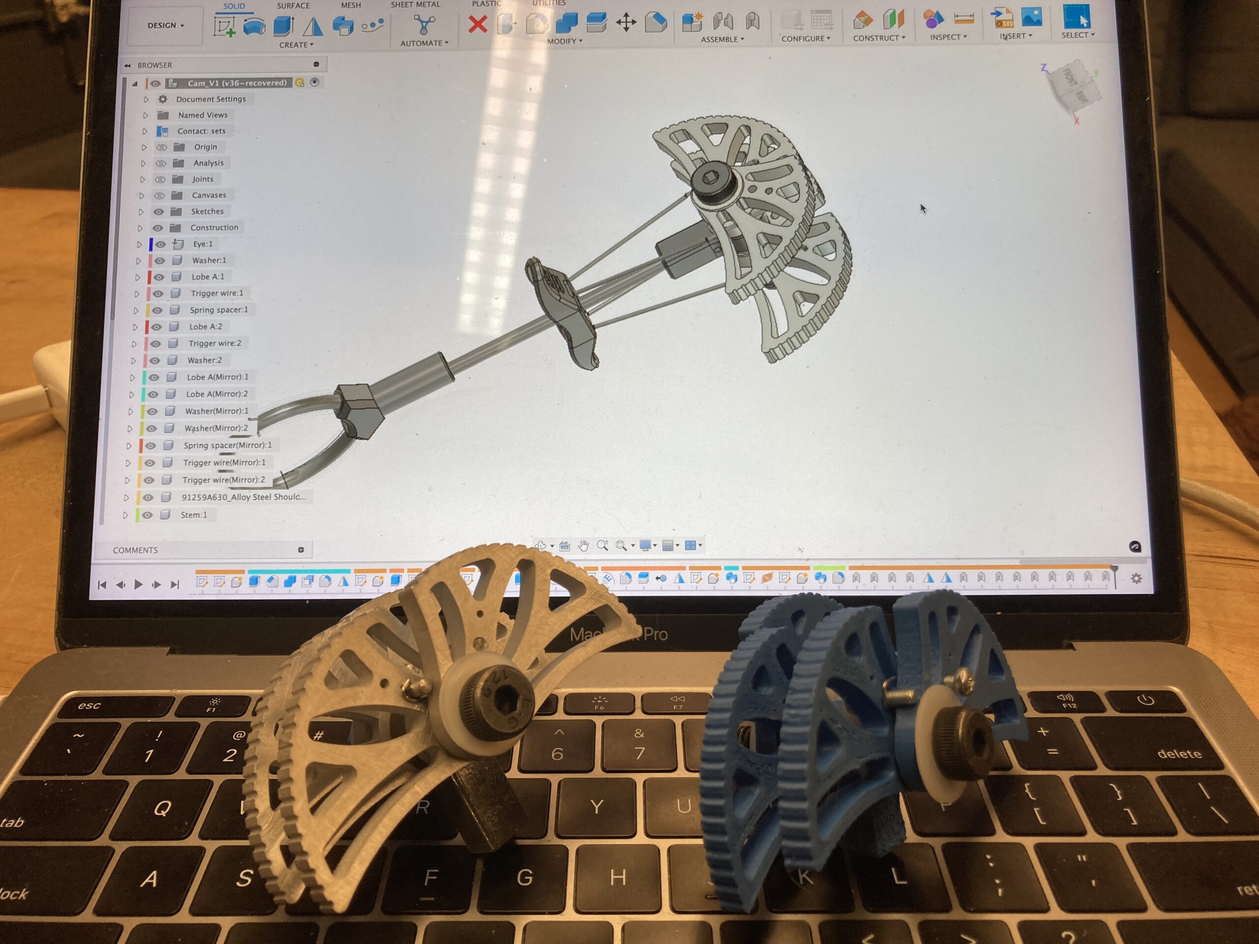
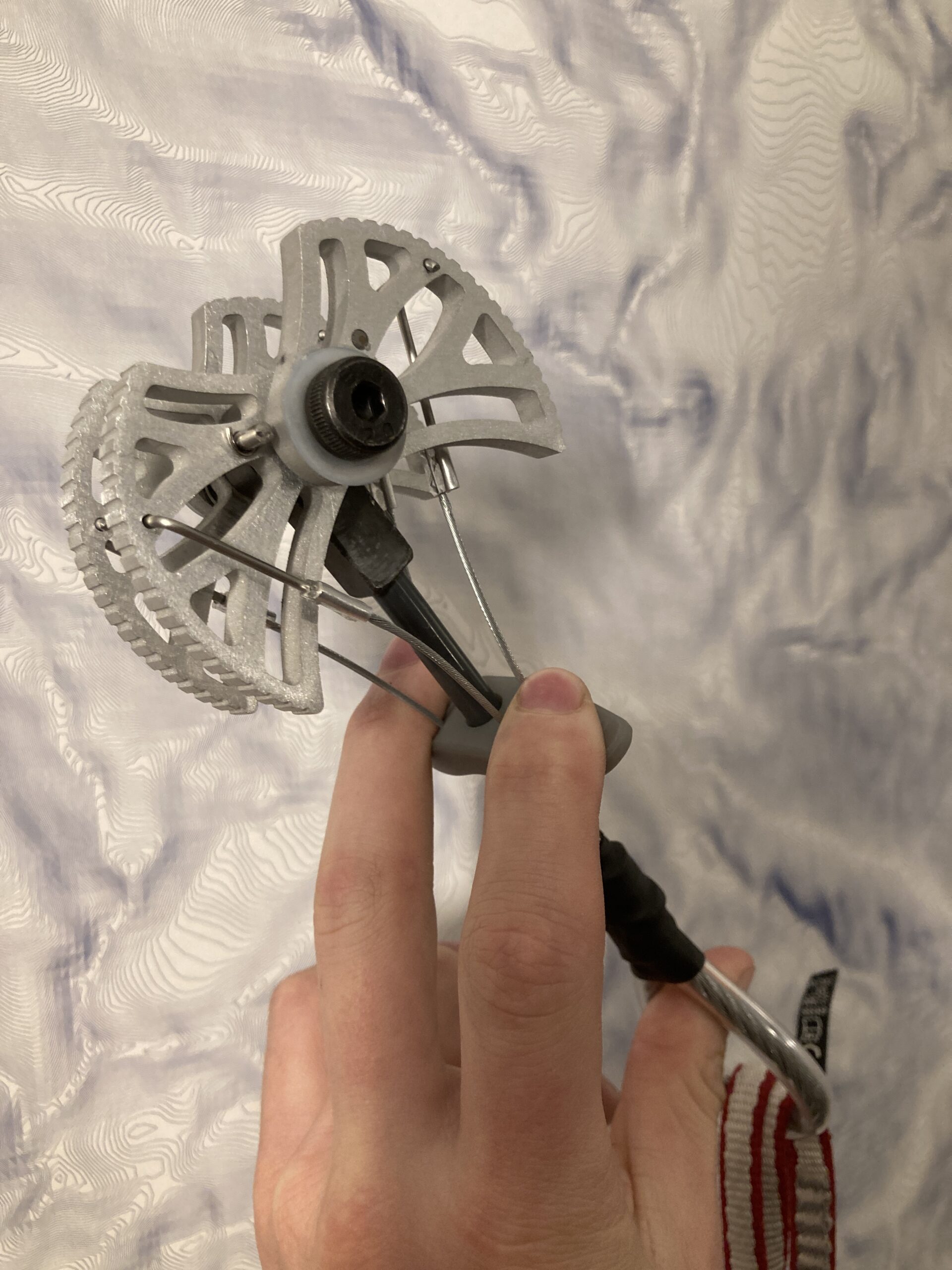
Final Assembly
With all 31 parts manufactured, the cam can be assembled. After building my first one, I designed and built a second smaller cam, making small improvements based on the learnings of the first attempt. Next step, testing the designs to check my calculations and manufacturing but the final products are beautiful!
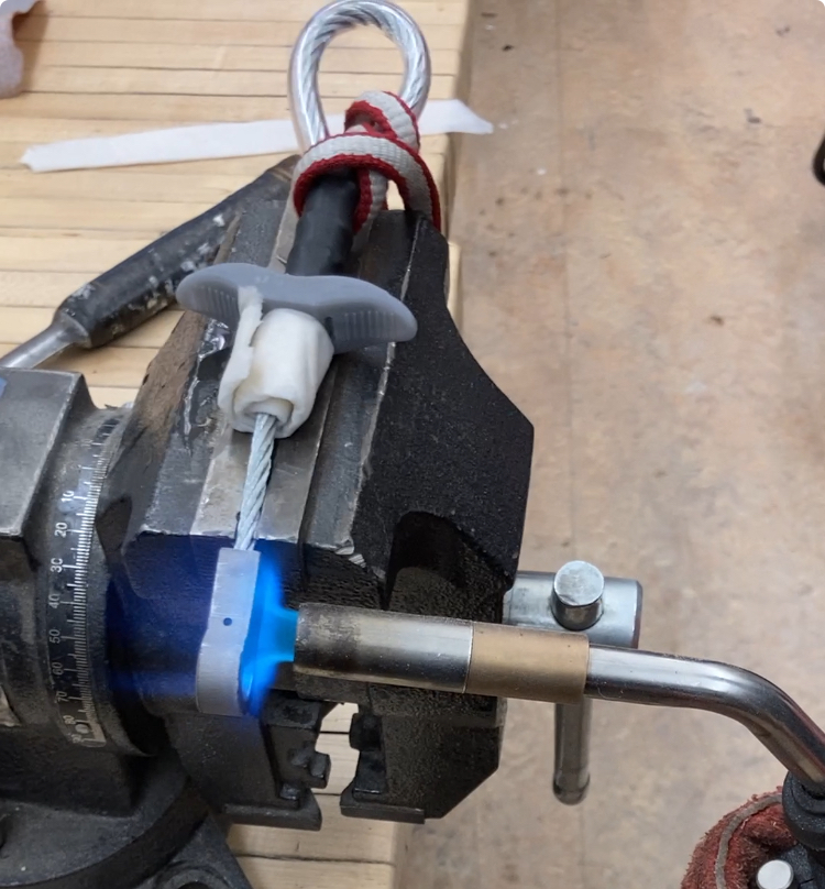
Testing
To test the cams I used a hydraulic pull tester at Dark Arts Splicing‘s shop . One end of the cam is attached to the hydraulic ram by the thumb loop using a sling while the other end cams into place in a custom jig.
Results
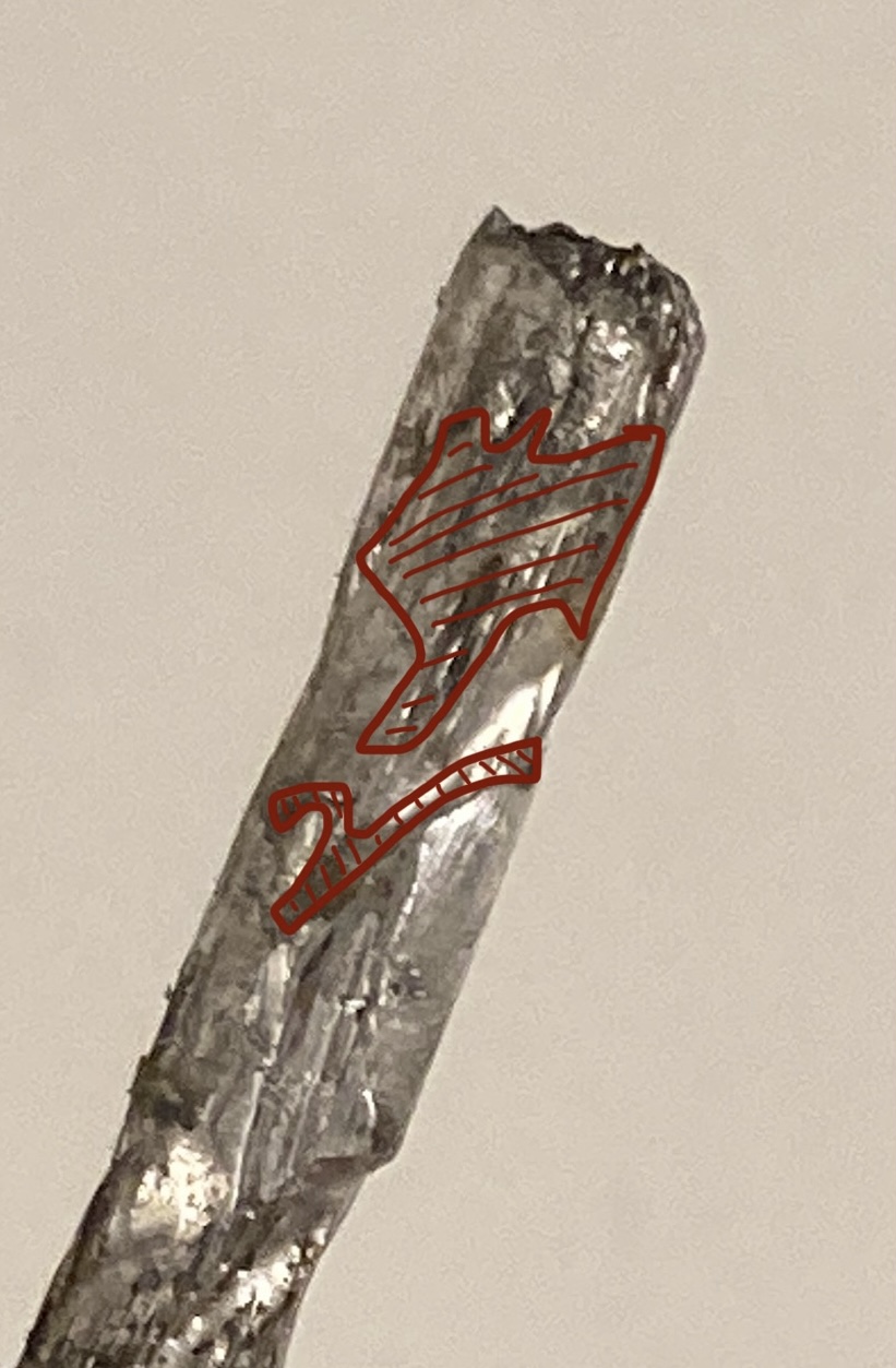
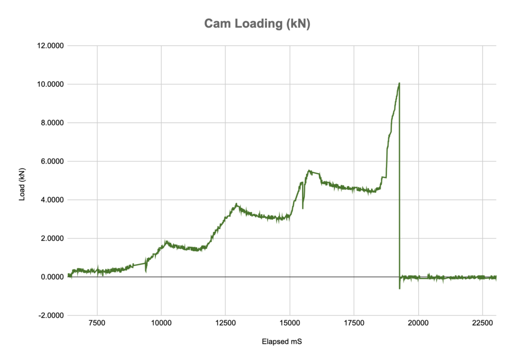
The cam was designed to take 8kN of loading. Past 8kN, the shaft that holds the lobes and eye of the cam together, would fail due to the a bending moment from the cam lobes as predicted by calculations. That said, I belived the brazed joint would fail first due to manufacturing defects hidden in the braze.
At 10kN the cam failed catastrophically when the brazed joint connecting the stem to the eye gave way. Further inspection of the failure revealed only 60% of the braze had been successful resulting in its reduced strength. I have since identified and implemented improved methods for brazing in my subsequent cams.
The cams performance, at 10kN surpassed my design goals and is sufficiently strong to catch a rock climbing fall!
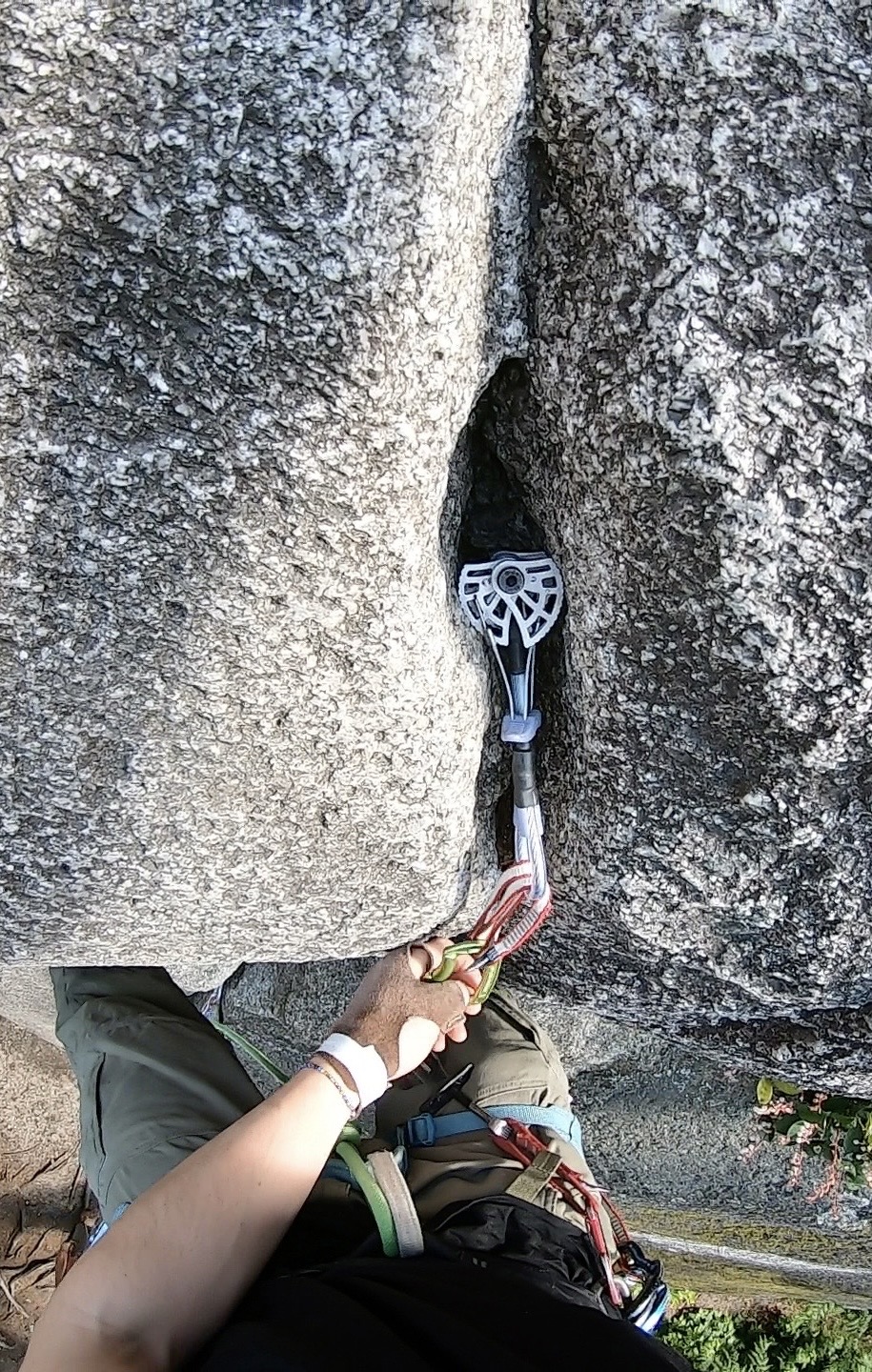
Outdoor Testing and Use
Having tested my cam “in the lab” it was time to take them outside. To test them outside I found a climb with an overhang and lots of options for climbing protection. By placing three commercial cams below my cam I could test falling on my cam without the risk of injury if my cam failed. The fall in the video is a relatively small fall but is representative of normal use for the cam. The cam holds the fall with almost no movement and took no damage. Success! Maybe a bigger test fall is in order…